At Nordes Oy, our commitment to engineering excellence drives us to continuously refine and optimize the mechanical designs of critical components. One of the key tools in our arsenal is Finite Element Analysis (FEA), which allows us to thoroughly evaluate and enhance the performance of complex structures.
In this article, we’ll take you through the sophisticated processes we employ to ensure that components like the high-efficiency induction motor we analyze are not only robust but also optimized for performance, durability, and efficiency.
Mechanical Design of the High-Efficiency Induction Motor
The motor in the analysis is a high-efficiency induction motor, designed for applications requiring precision, reliability, and energy efficiency. The design features several key mechanical elements that are crucial for its performance:
- Stator and Rotor Assembly: The heart of the motor, where electrical energy is converted into mechanical motion. Ensuring the structural integrity of these components under operational loads is essential.
- Cooling Fins: Designed to dissipate heat, these fins are vital for maintaining operational temperatures within safe limits, preventing overheating, and ensuring longevity.
- Housing: The motor’s housing must be robust enough to protect internal components while minimizing weight for efficiency. Critical stress regions, particularly around the mounting points, are a focus during analysis to ensure the motor can withstand operational loads without failure.
Challenges in Induction Motor Design:
- Thermal Management: Effective heat dissipation is critical to prevent thermal degradation of materials and ensure consistent performance. Velocity magnitude contours are analyzed to assess airflow patterns around the motor, crucial for evaluating the cooling fins' effectiveness.
- Vibration and Shock Resistance: The motor must withstand dynamic loads without compromising its structural integrity or performance.
- Material Optimization: Achieving the right balance between material strength and weight is essential for both performance and cost efficiency.
Step-by-Step FEA Approach at Nordes Oy
To address these challenges, Nordes Oy employs a meticulous FEA process that integrates mechanical design with advanced simulation techniques. Here’s how we approach it:
1. Pre-Processing
- Geometry Simplification & Cleanup: The first step involves simplifying the motor’s complex geometry without losing critical details that affect performance. This cleanup ensures the model is computationally efficient, focusing on the areas most prone to stress and deformation.
- Mid-Surface Extraction & Meshing: For components like the motor housing and cooling fins, we extract mid-surfaces to create a shell mesh, while more intricate parts like the rotor and stator may use tetrahedral or hexahedral meshes. This step is crucial in balancing accuracy with computational efficiency.
- Material Properties & Boundary Conditions: Accurate simulation requires a precise definition of material properties and boundary conditions. For instance, the motor’s aluminum housing is modeled with its exact thermal conductivity and strength characteristics, while boundary conditions simulate operational loads, such as rotational forces and thermal gradients.
2. FEA Stress and Thermal Analysis
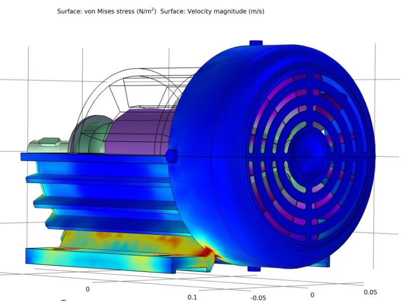
- Von Mises Stress Analysis: One of the critical analyses performed is the von Mises stress analysis, which helps identify areas within the motor that are subject to the highest stresses. The analysis highlights critical stress regions within the motor's housing, particularly around the mounting points, which are prone to stress concentrations under operational loads.
- Thermal Analysis: Given the importance of thermal management in motor design, we conduct a detailed heat transfer analysis. This analysis identifies hotspots where cooling may be insufficient, allowing us to redesign cooling fins or alter material properties to enhance heat dissipation. The thermal analysis also includes velocity magnitude contours, which indicate airflow patterns around the motor, crucial for assessing the effectiveness of the cooling fins in dissipating heat.
- Dynamic Response Analysis: Motors are often subject to dynamic loads, whether from vibration or shock. Our dynamic response analysis evaluates how these loads affect the motor, particularly focusing on resonance frequencies that could lead to failure.
- Velocity Magnitude Distribution: For motors that involve airflow for cooling, velocity magnitude analysis helps us understand how air flows around and through the motor, ensuring that cooling is effective and that no areas are left prone to overheating.
3. Post-Processing
- Results Interpretation: Post-analysis, we interpret the results to provide actionable insights. For instance, areas identified with high von Mises stress might prompt a design change, such as reinforcing the housing or adjusting the mounting points.
- Design Iteration: Based on the FEA results, we iterate on the design. This might involve altering the geometry of the cooling fins, adjusting material thickness, or modifying the motor’s overall structure to enhance durability and performance.
- Validation: Finally, we validate the design through comparison with experimental data or industry standards, ensuring that our FEA predictions are reliable and that the motor will perform as expected in real-world conditions.